Meridian C160assembly guide

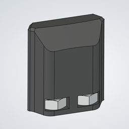
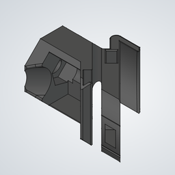
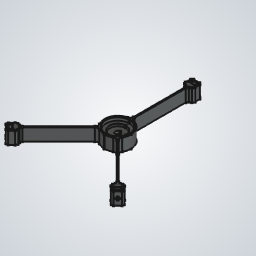
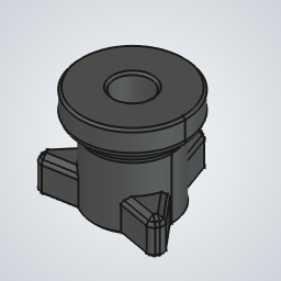
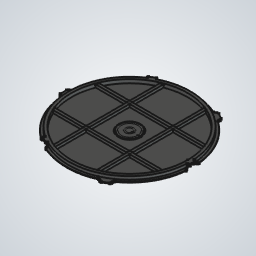
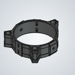
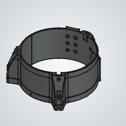
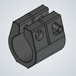
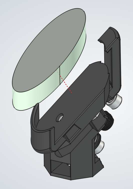
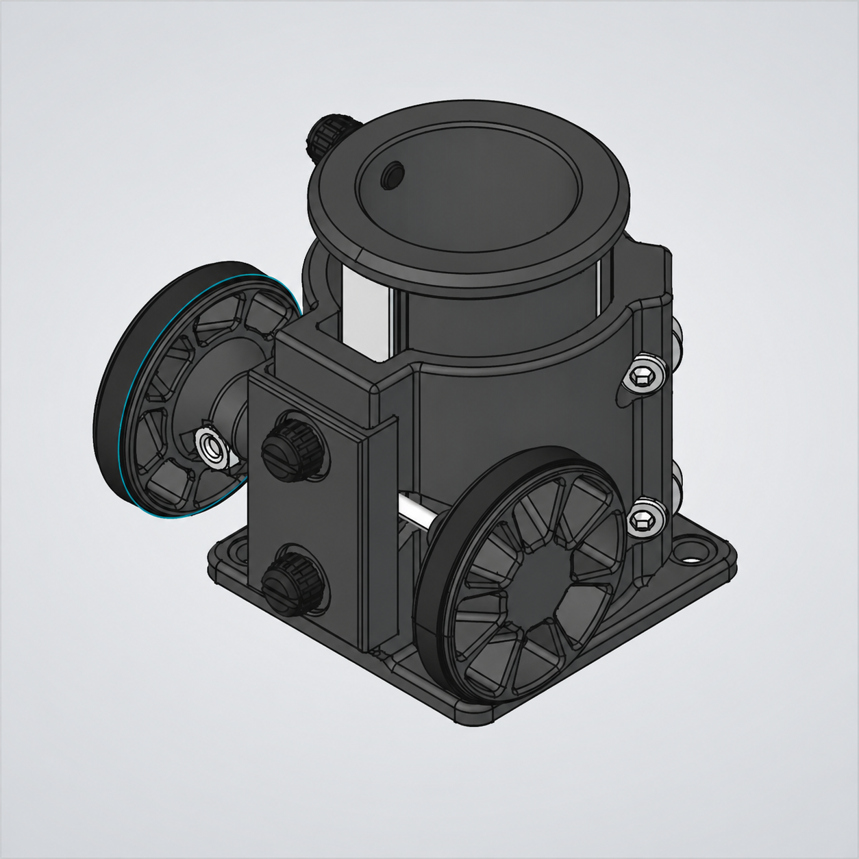
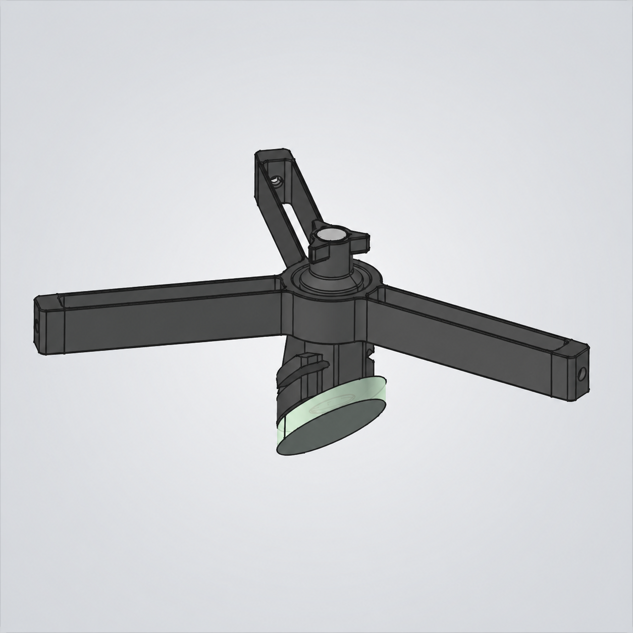
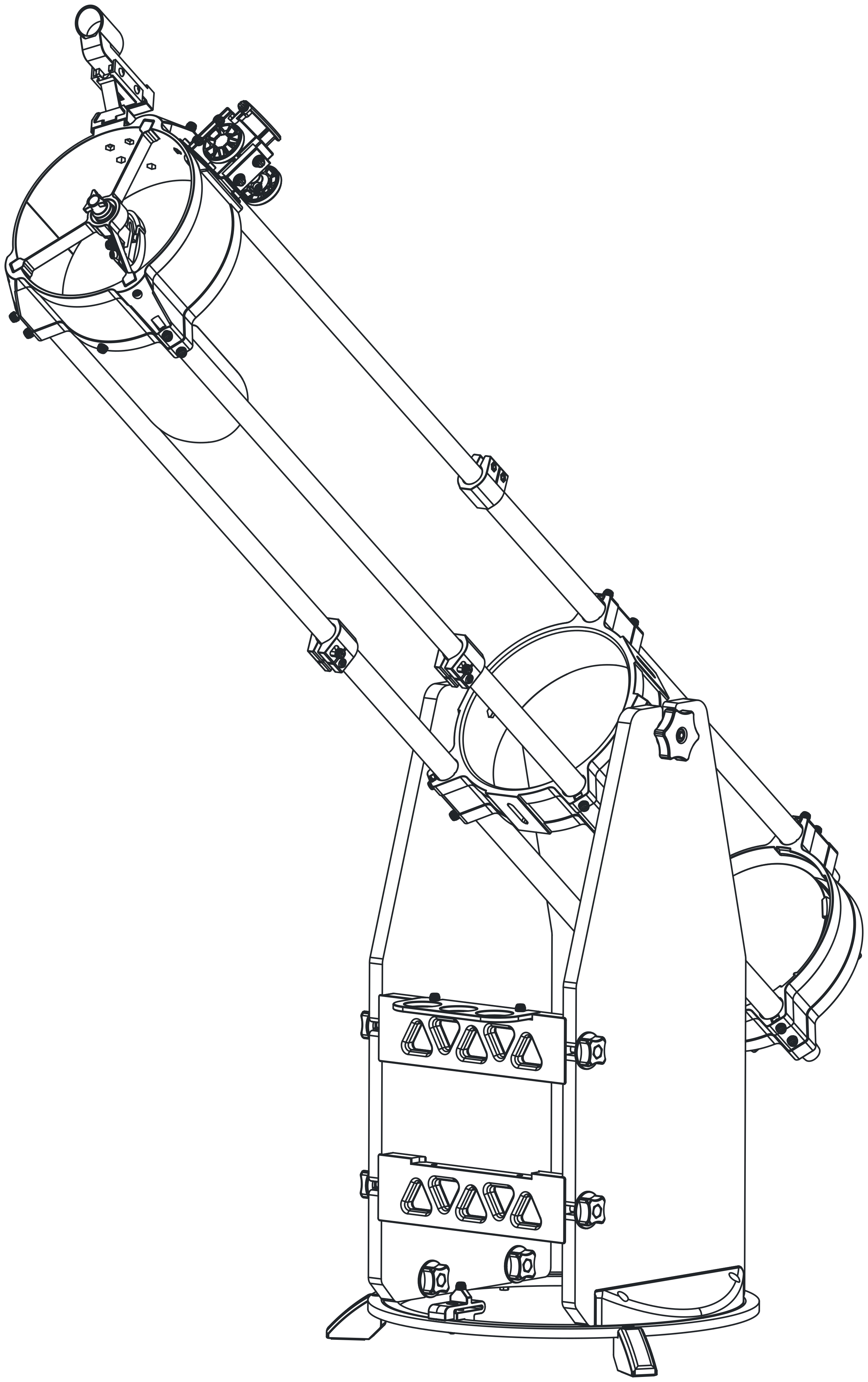
Meridian C160 product drawing

Safety

Read this safety information before assembly or use. These warnings cover hazards that can cause eye injury, cuts, pinching, or damage to the telescope if the instructions are not followed.

  • WARNING — Solar viewing hazard: Never look at or near the Sun through this telescope, finder, eyepiece, camera, or any other optical device. This telescope is not designed for solar observing, and no solar filter is provided or intended for use with it. Do not use the telescope for daytime observing, as there is a risk of accidentally pointing it at or near the Sun. Looking at the Sun through a telescope can cause instant, permanent eye injury or blindness. Eye damage may be painless and may not be noticed immediately.
  • WARNING — Not a toy: This product is not a toy. Recommended for ages 14 and older. Adult supervision is required during assembly and use by minors.
  • WARNING — Choking hazard: Small parts are present. Keep all loose parts, fasteners, packaging, and tools away from children under 3 years old.
  • CAUTION — Sharp edges: Printed, machined, or cut parts may have sharp edges or burrs. Handle parts carefully and deburr or sand sharp edges before use.
  • CAUTION — Pinch points: Moving joints, knobs, bearings, and sliding parts can pinch fingers. Keep hands clear while adjusting or tightening assemblies.
  • CAUTION — Assembly and tools: Assemble on a stable surface. Wear eye protection when cutting, sanding, drilling, or deburring. Do not overtighten fasteners into printed parts.
  • NOTICE — Pre-use inspection: Before each use, verify that all knobs, screws, mirrors, optical parts, and structural connections are secure.

Parts

Printed Parts

PartQty
Altitude clutch axle left1Altitude clutch axle left thumbnail
Altitude clutch axle right1Altitude clutch axle right thumbnail
Altitude clutch handle1Altitude clutch handle thumbnail
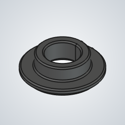
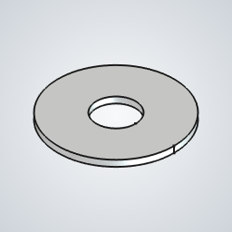
Altitude clutch washer1Altitude clutch washer thumbnail
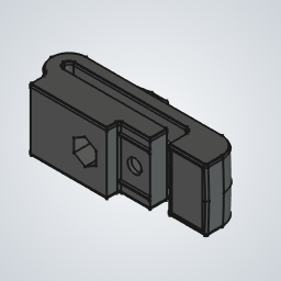
Finder mount1Finder mount thumbnail
Focuser base1Focuser base thumbnail
Focuser bridge1Focuser bridge thumbnail
Focuser knob2Focuser knob thumbnail
Focuser tube1Focuser tube thumbnail
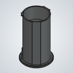
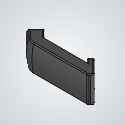
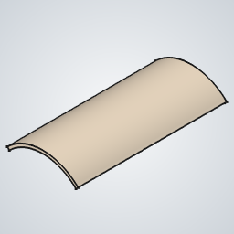
Light shield1Light shield thumbnail
Primary cell1Primary cell thumbnail
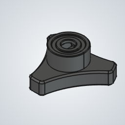
Primary cell knob3Primary cell knob thumbnail
Primary cell tab3Primary cell tab thumbnail
Secondary cell1Secondary cell thumbnail
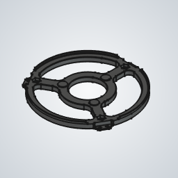
Secondary cell spider1Secondary cell spider thumbnail
Secondary cell spider knob1Secondary cell spider knob thumbnail
Secondary cell spring base1Secondary cell spring base thumbnail
Secondary cell tab1Secondary cell tab thumbnail
Stand anchor2Stand anchor thumbnail
Stand azimuth clutch1Stand azimuth clutch thumbnail
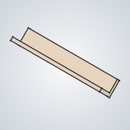
Stand eyepiece tray1Stand eyepiece tray thumbnail
Stand feet3Stand feet thumbnail
Stand front2Stand front thumbnail
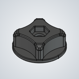
Stand knob8Stand knob thumbnail
Telescope bottom1Telescope bottom thumbnail
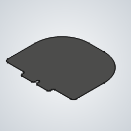
Telescope bottom lid1Telescope bottom lid thumbnail
Telescope center1Telescope center thumbnail
Telescope top1Telescope top thumbnail
Tube clamp3Tube clamp thumbnail

Hardware

PartQty
3 mmx60 pin13 mmx60 pin thumbnail
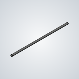
Aluminum rail for focuser3Aluminum rail for focuser thumbnail
Base bearing1Base bearing thumbnail
Bearing 6042RS4Bearing 6042RS thumbnail
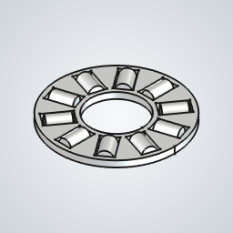
Bearing AXK08193Bearing AXK0819 thumbnail
Felt tape piece3Felt tape piece thumbnail
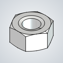
M4 nut63M4 nut thumbnail
M4 washer8M4 washer thumbnail
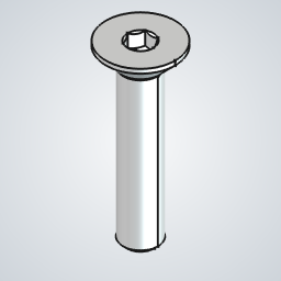
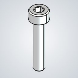
M4x10 socket head screw22M4x10 socket head screw thumbnail
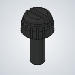
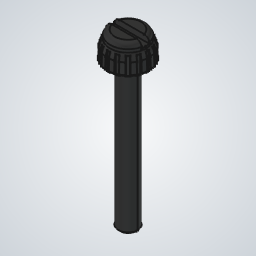
M4x10 thumbscrew26M4x10 thumbscrew thumbnail
M4x20 cone head screw3M4x20 cone head screw thumbnail
M4x20 socket head screw12M4x20 socket head screw thumbnail
M4x30 thumbscrew4M4x30 thumbscrew thumbnail
M6 nut25M6 nut thumbnail
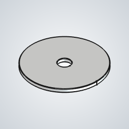
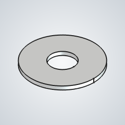
M6 washer 18mm wide10M6 washer 18mm wide thumbnail
M6 washer 40mm wide2M6 washer 40mm wide thumbnail
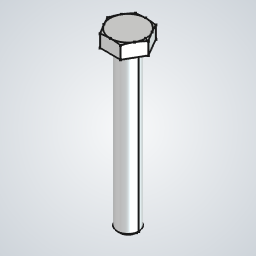
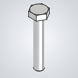
M6x35 hex head screw13M6x35 hex head screw thumbnail
M6x45 hex head screw1M6x45 hex head screw thumbnail
M8 washer 19mm wide6M8 washer 19mm wide thumbnail
Primary mirror1Primary mirror thumbnail
PTFE sheet for azimuth clutch1PTFE sheet for azimuth clutch thumbnail
PTFE sheet for focuser1PTFE sheet for focuser thumbnail
PTFE sheet for tube3PTFE sheet for tube thumbnail
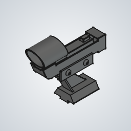
Red dot finder1Red dot finder thumbnail
Rubber feet3Rubber feet thumbnail
Secondary mirror1Secondary mirror thumbnail
Silicone band 20x52Silicone band 20x5 thumbnail
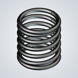
Spring 0.9mm1Spring 0.9mm thumbnail
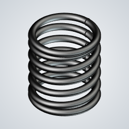
Spring 1.2mm3Spring 1.2mm thumbnail
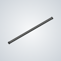
Tube narrow3Tube narrow thumbnail
Tube wide3Tube wide thumbnail
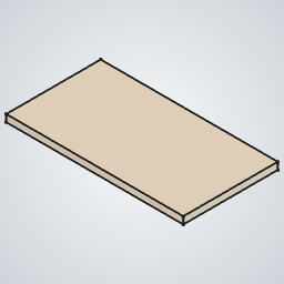
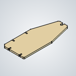
Wooden stand side2Wooden stand side thumbnail

Tools

  • 2.5mm hex key
  • 3mm hex key
  • Hex jig (printed)
  • Ruler
  • Scissors
  • Clear, stable, soft work surface, such as cardboard or a rug

Assemblies

Build each section in order, then move on to the next assembly.

Stand Knob (x8)

PartQty
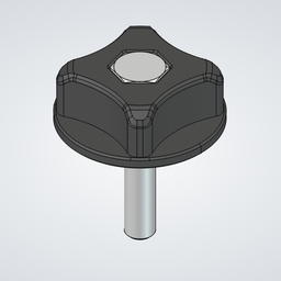
Stand knob1Stand knob thumbnail
M6x35 hex head screw1M6x35 hex head screw thumbnail
M6 washer 18mm wide1M6 washer 18mm wide thumbnail
M6 nut1M6 nut thumbnail
Stand Knob (x8) assembly
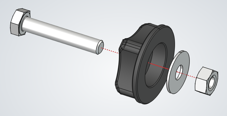
  1. 1.Insert the screw into the knob.
  2. 2.From the other side, add the 18mm washer and thread the nut onto the screw.
  3. 3.Spin the nut down to the bottom, then use the printed wrench to tighten it.

Stand Anchor (x2)

PartQty
Stand anchor1Stand anchor thumbnail
Stand knob assembly2Stand knob assembly thumbnail
M6 nut2M6 nut thumbnail
M4x20 socket head screw2M4x20 socket head screw thumbnail
M4 washer4M4 washer thumbnail
1Stand Anchor (x2) assembly
2Stand Anchor (x2) assembly
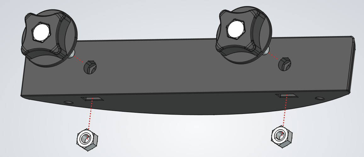
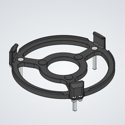
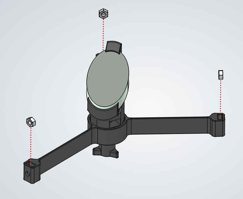
  1. 1.a.Insert the two nuts into their slots.
    b.Thread the knobs into the nuts, leaving about 1 cm of space from the anchor itself.
  2. 2.Place each M4 screw through two M4 washers and into position. These will attach the anchor to the base later.

Stand Feet (x3)

PartQty
Stand feet1Stand feet thumbnail
M4 nut1M4 nut thumbnail
Felt tape piece1Felt tape piece thumbnail
Stand Feet (x3) assembly
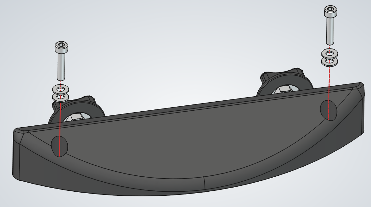
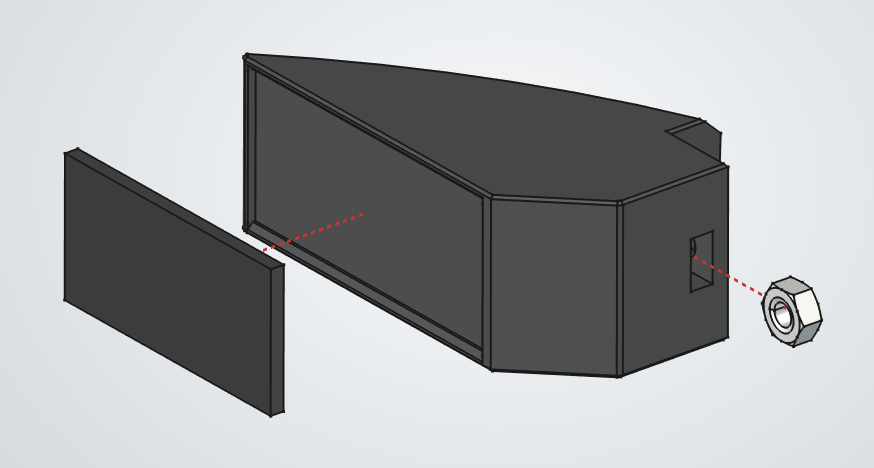
  1. 1.Insert the M4 nut into the side pocket of the foot.
  2. 2.Take a piece of felt tape and stick it onto the flat bottom face.
  3. 3.Repeat for the two other feet.

Stand Azimuth Clutch

PartQty
M4 nut1M4 nut thumbnail
M4x30 thumbscrew1M4x30 thumbscrew thumbnail
PTFE sheet for azimuth clutch1PTFE sheet for azimuth clutch thumbnail
M4x20 socket head screw1M4x20 socket head screw thumbnail
Stand azimuth clutch1Stand azimuth clutch thumbnail
Stand Azimuth Clutch assembly
  1. 1.Insert the M4 nut into the underside pocket.
  2. 2.Thread the thumbscrew through the raised part and into the nut.
  3. 3.Install the screw through the round hole in the top of the clutch.
  4. 4.Cut a 1.5 cm by 0.8 cm piece from the PTFE sheet, peel off the backing, and stick it onto the flat contact face.

Stand Base

PartQty
Base bearing1Base bearing thumbnail
M4x20 cone head screw3M4x20 cone head screw thumbnail
Stand anchor assembly2Stand anchor assembly thumbnail
M4 nut5M4 nut thumbnail
Stand azimuth clutch assembly1Stand azimuth clutch assembly thumbnail
Stand feet assembly3Stand feet assembly thumbnail
1Stand Base assembly
2Stand Base assembly
3Stand Base assembly
4Stand Base assembly
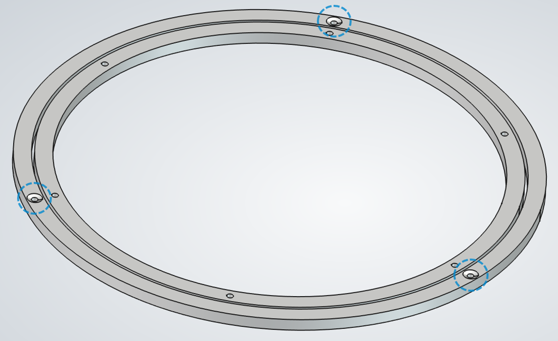
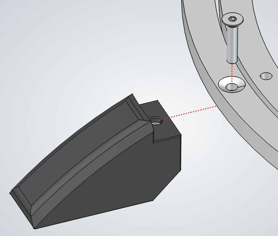
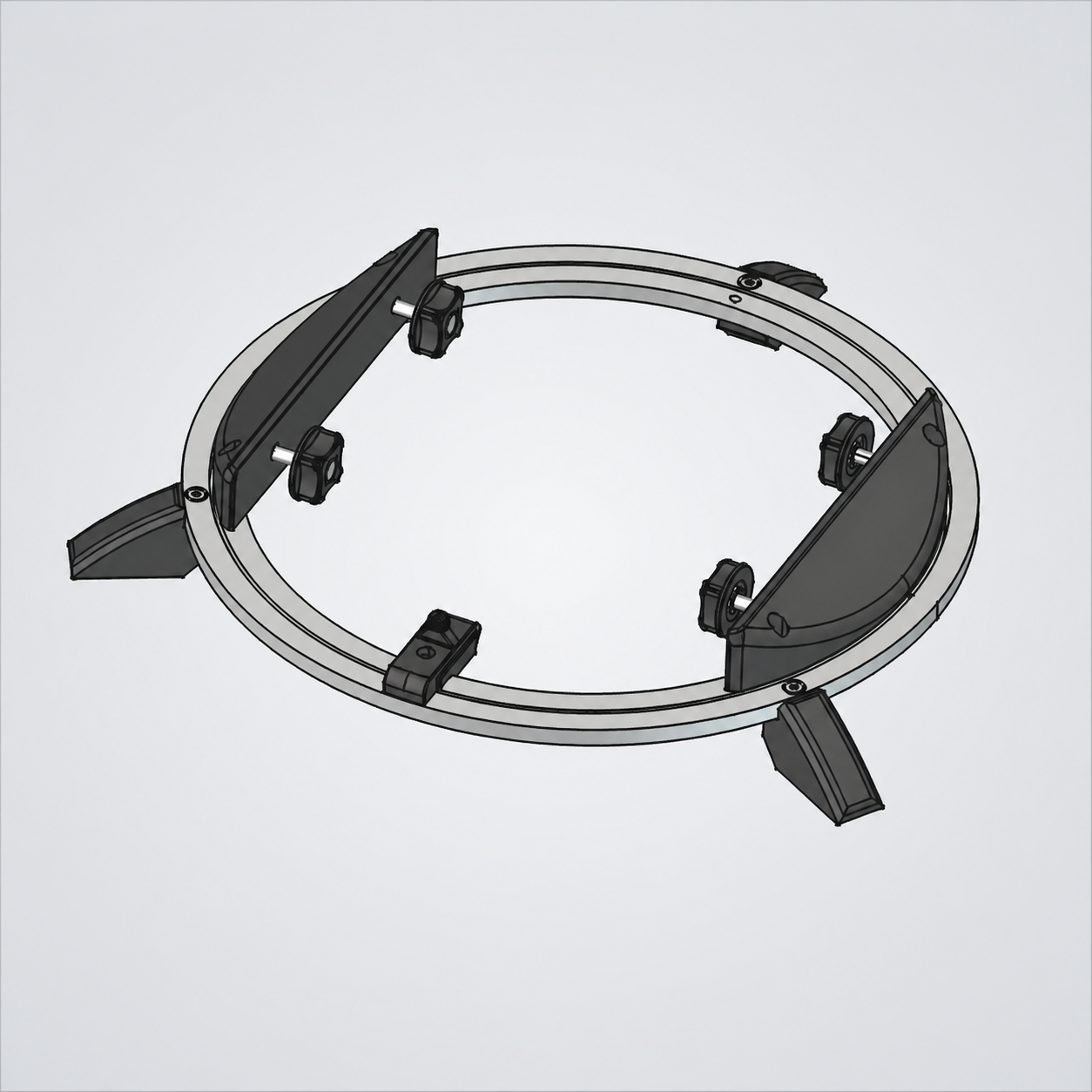
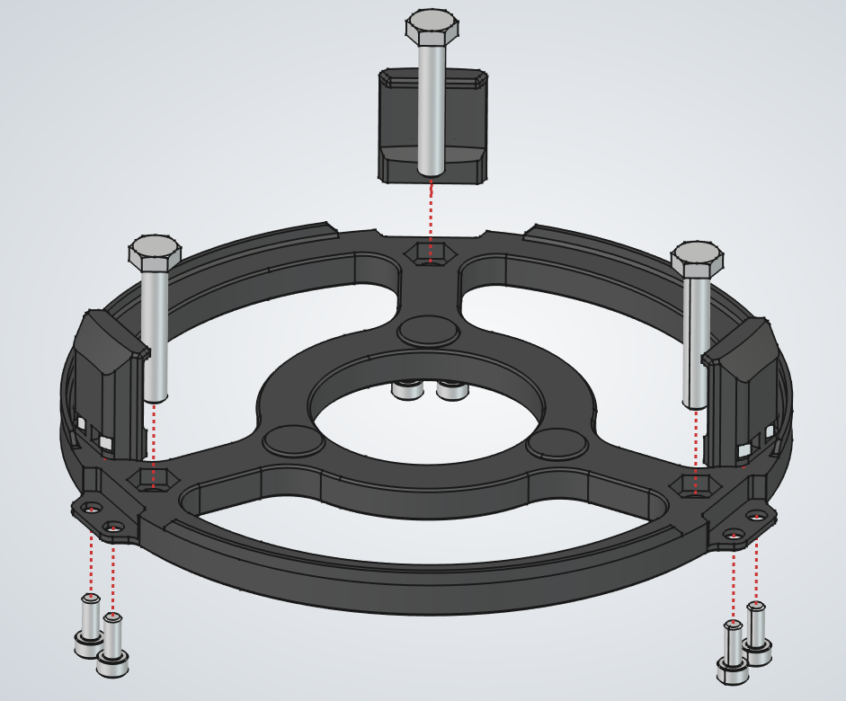
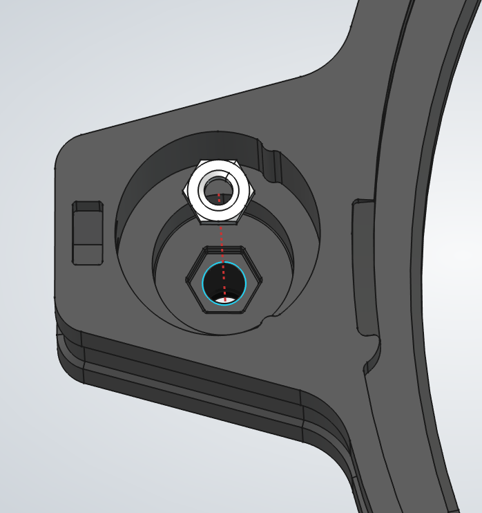
  1. 1.Place the base bearing with the countersunk holes of the outer ring facing up.
  2. 2.a.For each foot, place it under a matching hole and insert the screw from above.
    b.Press the foot fully into the base bearing, then tighten the screw with the 2.5mm hex key.
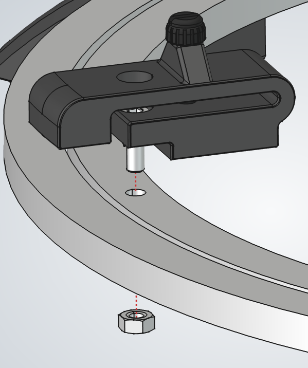
  3. 3.Place the azimuth clutch over the remaining hole in the outer ring, then add the nut on the other side and tighten the screw.
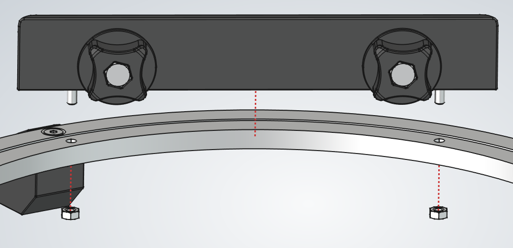
  4. 4.a.Place each anchor against the outer ring and insert its screws through the matching holes.
    b.While tightening the nuts on the other side, press the anchor outward so it sits near the edge of the ring.

Stand Front

PartQty
Stand front1Stand front thumbnail
Stand knob assembly2Stand knob assembly thumbnail
M4x10 thumbscrew2M4x10 thumbscrew thumbnail
M4 nut2M4 nut thumbnail
Stand eyepiece tray1Stand eyepiece tray thumbnail
M6 nut2M6 nut thumbnail
1Stand Front assembly
2Stand Front assembly
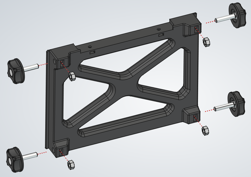
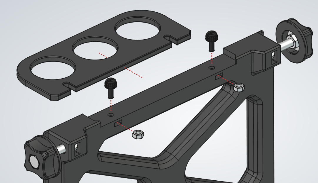
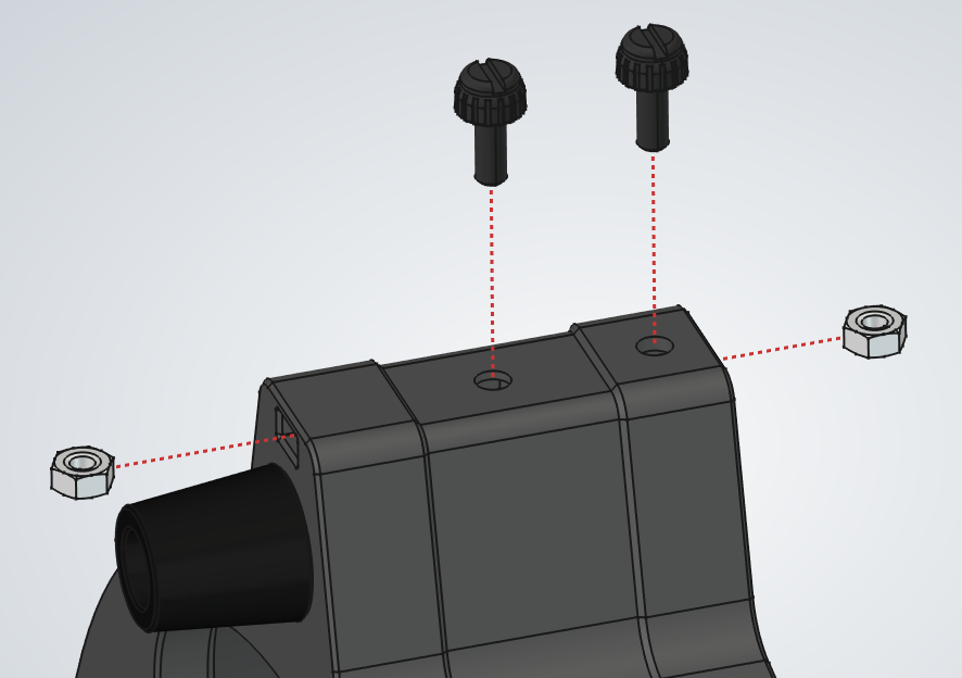
  1. 1.a.Insert the four M6 nuts into the side pockets.
    b.Thread the knobs into the nuts, leaving about 1 cm of space from the panel itself.
  2. 2.a.Insert the M4 nuts into their slots.
    b.Thread the thumbscrews into the front panel, leaving enough space for the eyepiece tray to slide under them.
    c.Slide the eyepiece tray into place under the thumbscrews.

Stand Assembly

PartQty
Stand base assembly1Stand base assembly thumbnail
Wooden stand side2Wooden stand side thumbnail
Stand front assembly1Stand front assembly thumbnail
Stand front without tray assembly1Stand front without tray assembly thumbnail
1Stand Assembly assembly
2Stand Assembly assembly
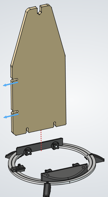
  1. 1.Slide one of the side boards under the base knobs and lock it in place. Orient the board so its slots face toward the azimuth clutch, as shown by the arrows. Repeat for the other side.
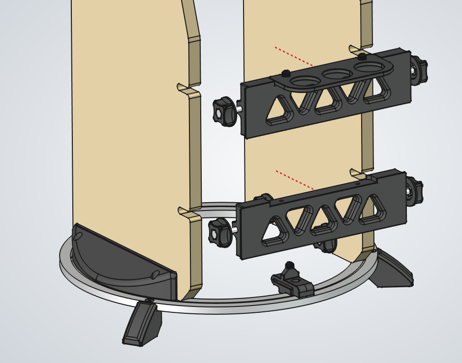
  2. 2.Slide the front panels in so their knobs pass through the slots in the side boards, then lock the knobs.

Primary Cell Tab (x3)

PartQty
Primary cell tab1Primary cell tab thumbnail
M4 nut2M4 nut thumbnail
Primary Cell Tab (x3) assembly
  1. 1.Insert the two M4 nuts into the pockets at the bottom of the tab.
  2. 2.Press the nuts fully into place so they sit flush.
  3. 3.Repeat for all three primary cell tabs.

Primary Cell

PartQty
Primary cell1Primary cell thumbnail
M6x35 hex head screw3M6x35 hex head screw thumbnail
Primary cell tab assembly3Primary cell tab assembly thumbnail
M4x10 socket head screw6M4x10 socket head screw thumbnail
Primary Cell assembly
  1. 1.Thread two M4 nuts onto the tab just enough to hold it in place. Thread them just enough so the screws will not fall off, but keep plenty of space for the tab to pivot.
  2. 2.Repeat for the remaining tabs.
  3. 3.Place the three hex screws into their recesses.

Bottom Assembly

PartQty
Telescope bottom1Telescope bottom thumbnail
Primary cell knob3Primary cell knob thumbnail
Rubber feet3Rubber feet thumbnail
M4x20 socket head screw3M4x20 socket head screw thumbnail
M4 nut9M4 nut thumbnail
M6 nut3M6 nut thumbnail
M4x10 thumbscrew6M4x10 thumbscrew thumbnail
Primary cell assembly1Primary cell assembly thumbnail
Spring 1.2mm3Spring 1.2mm thumbnail
Telescope bottom lid1Telescope bottom lid thumbnail
Primary mirror1Primary mirror thumbnail
1Bottom Assembly assembly
2Bottom Assembly assembly
3Bottom Assembly assembly
4Bottom Assembly assembly
5Bottom Assembly assembly
6Bottom Assembly assembly
7Bottom Assembly assembly
8Bottom Assembly assembly
9Bottom Assembly assembly
10Bottom Assembly assembly
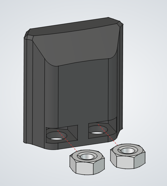
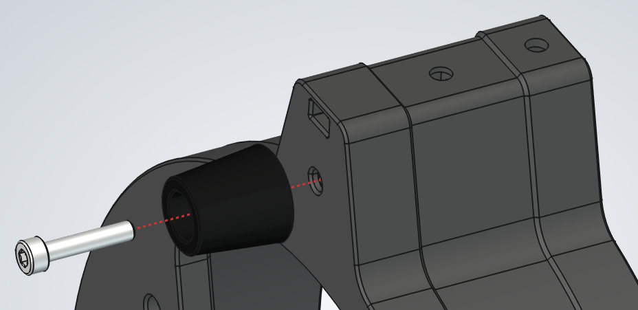
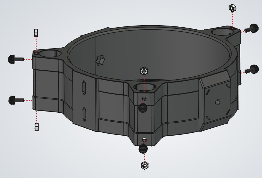
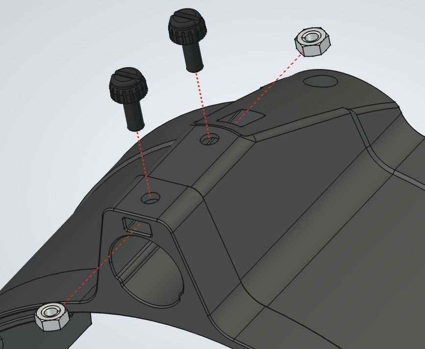
  1. 1.From above, insert an M4 nut into its pocket in one of the tube openings.
  1. 2.From below, attach a rubber foot with a long screw. Repeat for the other two feet.
  1. 3.Insert the two nuts and screws into their pockets in the tube slot. Repeat for all three sides.
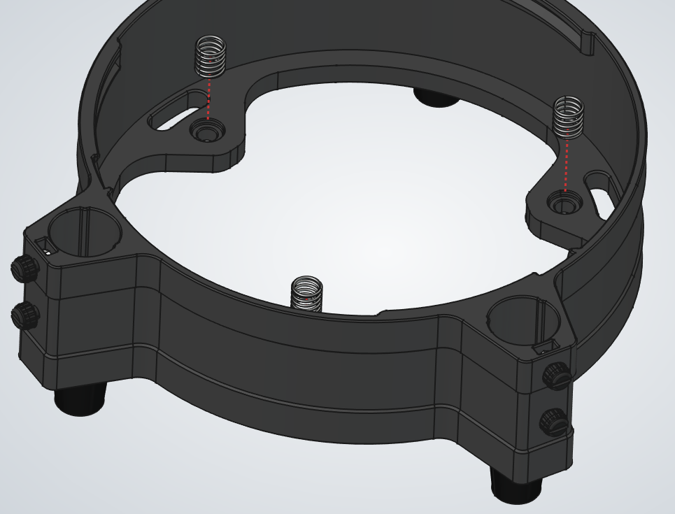
  1. 4.Set the springs into the primary cell support points.
  1. 5.Lower the primary cell so the hex screws pass through the springs, then rest it on the springs.
  1. 6.Install the knobs.
    1. a.Press down on the primary cell until the screw protrudes from the other side.
    2. b.Thread the knobs into place using M6 nuts.
    3. c.Repeat for all three knobs.
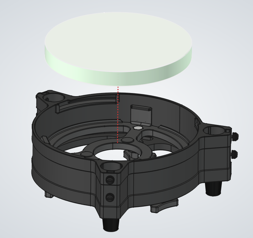
  1. 7.Install the mirror.
    1. a.Single-use gloves are recommended for this step to avoid fingerprints on the mirror. With or without gloves, avoid touching the mirror surface.
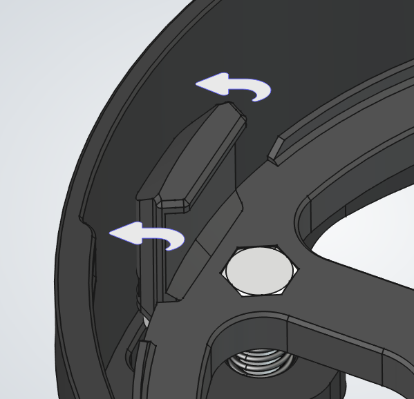
    2. b.Pivot the tabs to the side so the mirror can drop into place.
    3. c.Lower the mirror into the cell.
    4. d.Pivot the tabs back over the mirror.
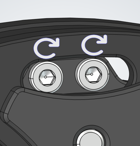
    5. e.From the back, tighten the screws shown in image 9. Press each tab against the mirror while tightening to make sure the mirror is seated correctly.
    6. f.You may place the entire assembly on its side to do this, but keep the tab you are holding on top so the mirror cannot fall out.
    7. g.Repeat for all three tabs.
    8. h.The mirror should be able to move slightly. This is normal and prevents it from being under stress. The tabs are only there to keep it from falling out.
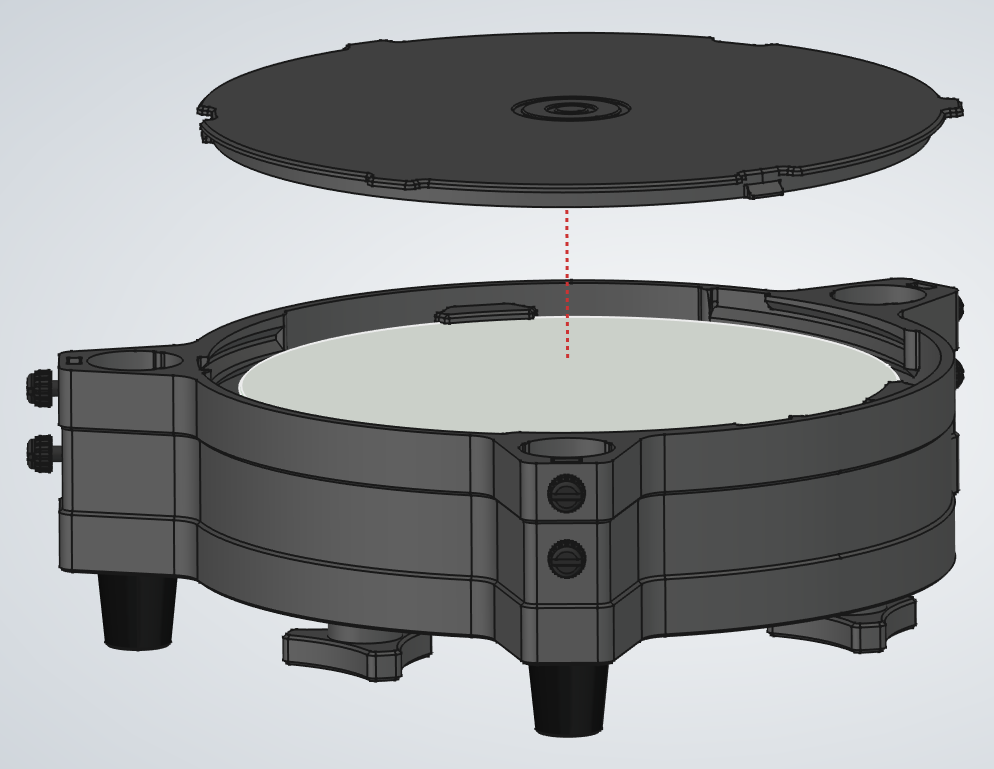
  1. 8.Place the lid over the mirror opening and rotate to lock it in place.

Center Assembly

PartQty
Telescope center1Telescope center thumbnail
Altitude clutch washer1Altitude clutch washer thumbnail
Altitude clutch handle1Altitude clutch handle thumbnail
Altitude clutch axle left1Altitude clutch axle left thumbnail
M6x45 hex head screw1M6x45 hex head screw thumbnail
M6 washer 40mm wide2M6 washer 40mm wide thumbnail
M6x35 hex head screw1M6x35 hex head screw thumbnail
M6 washer 18mm wide2M6 washer 18mm wide thumbnail
M6 nut5M6 nut thumbnail
Bearing AXK08191Bearing AXK0819 thumbnail
M8 washer 19mm wide2M8 washer 19mm wide thumbnail
Altitude clutch axle right1Altitude clutch axle right thumbnail
M4x10 thumbscrew6M4x10 thumbscrew thumbnail
M4 nut6M4 nut thumbnail
1Center Assembly assembly
2Center Assembly assembly
3Center Assembly assembly
4Center Assembly assembly
5Center Assembly assembly
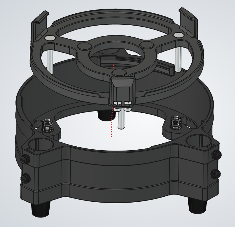
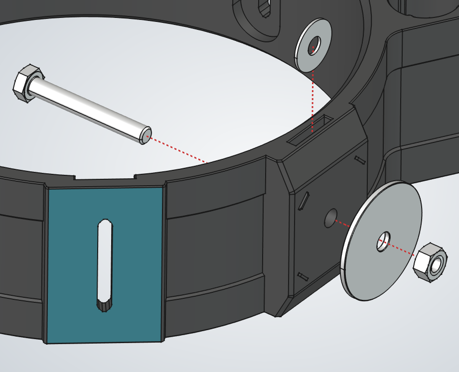
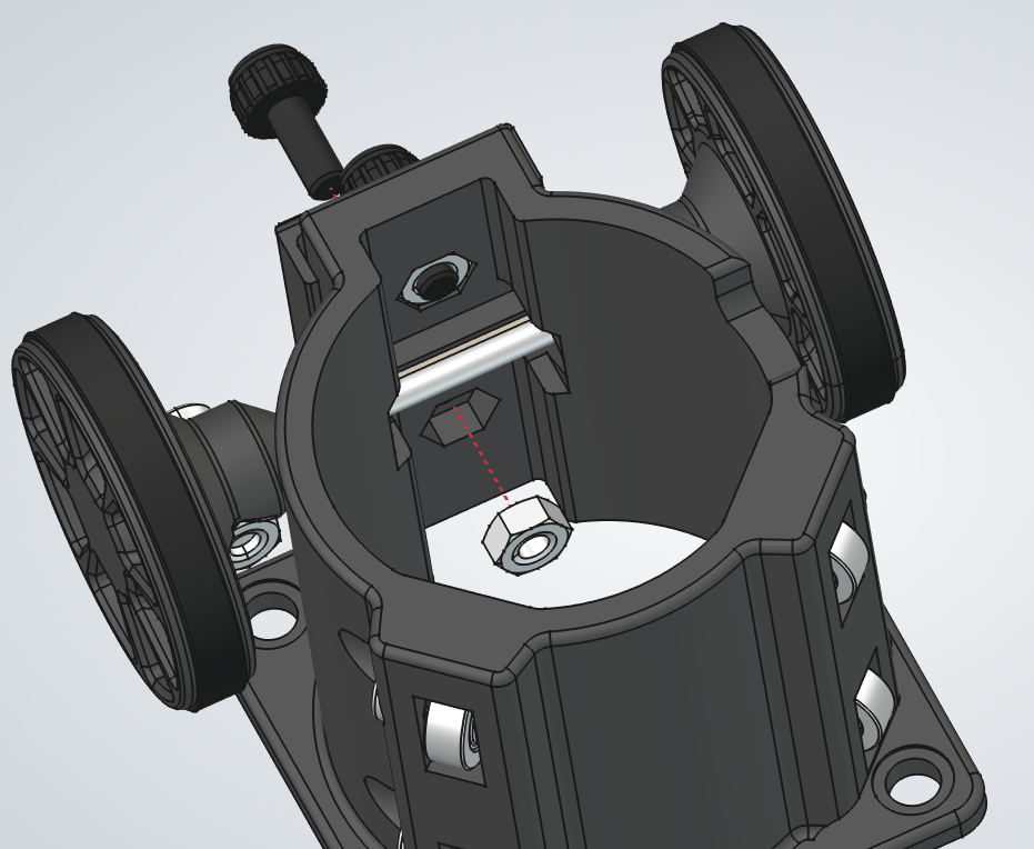
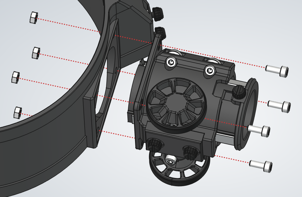
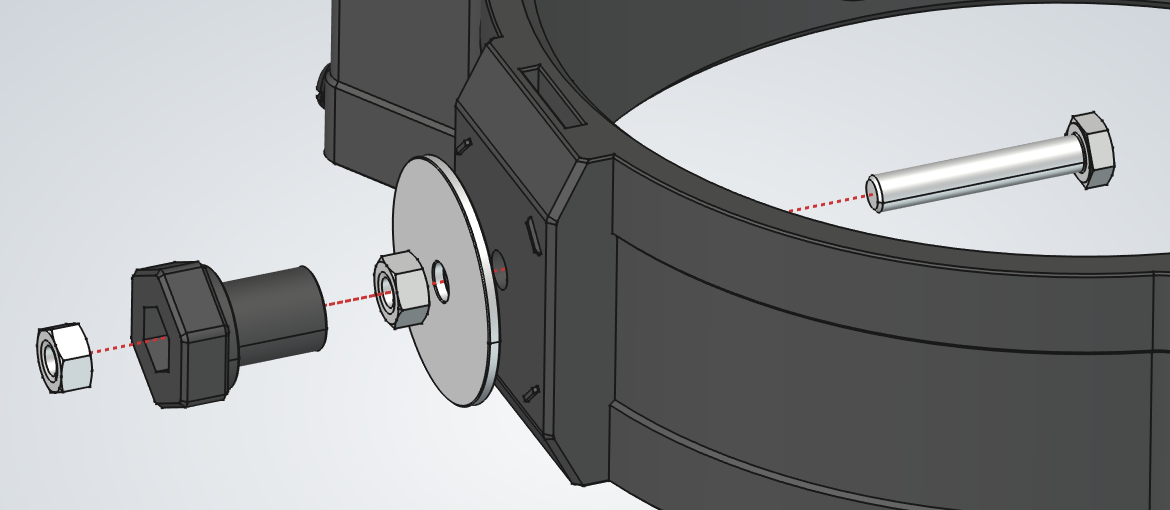
  1. 1.Insert the two nuts and screws into their pockets in the tube slot. Repeat for all three sides.
  1. 2.Find the side that is near the rail that is marked in blue.
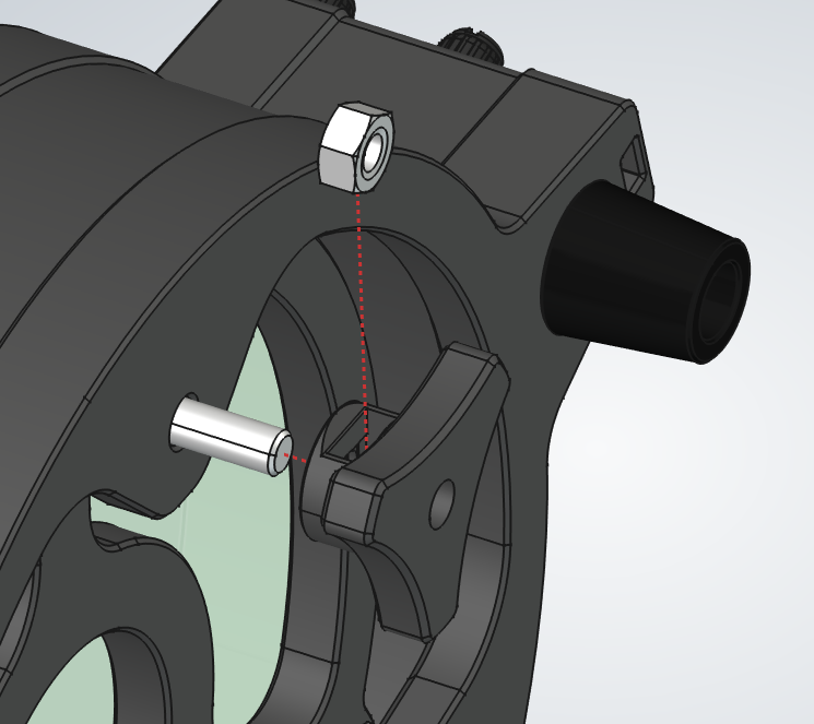
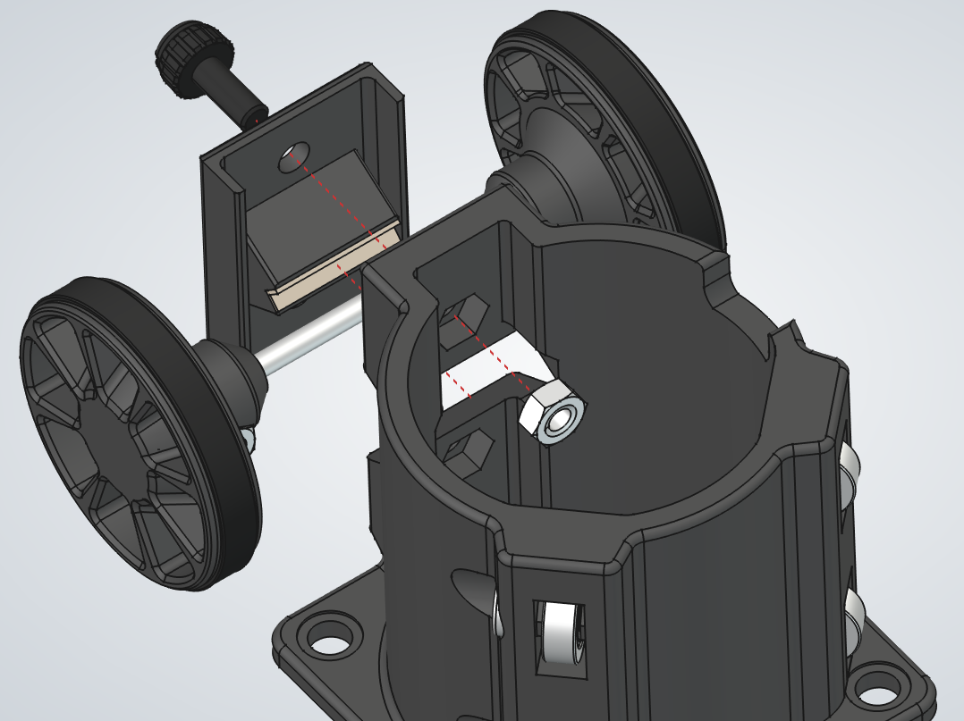
    1. a.Take an 18mm washer and slide it into its designated slot. Make sure this is an 18mm washer, not the 19mm washer used with the bearings.
    2. b.Insert the large 45mm hex screw through the washer, then add the 40mm washer and M6 nut from the other side. Make sure the large washer sits between the tabs.
    3. c.Tighten the nut with the printed wrench.
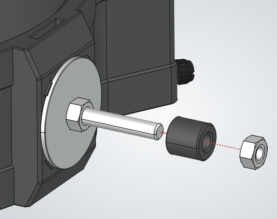
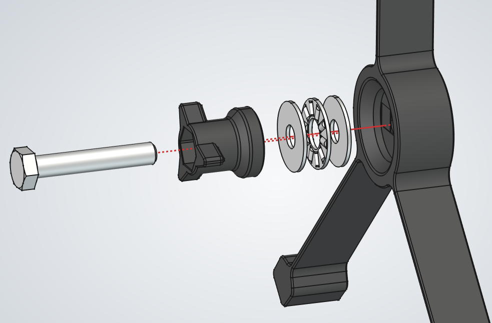
  1. 3.Add the right axle on top of the screw and lock it in place using another M6 nut.
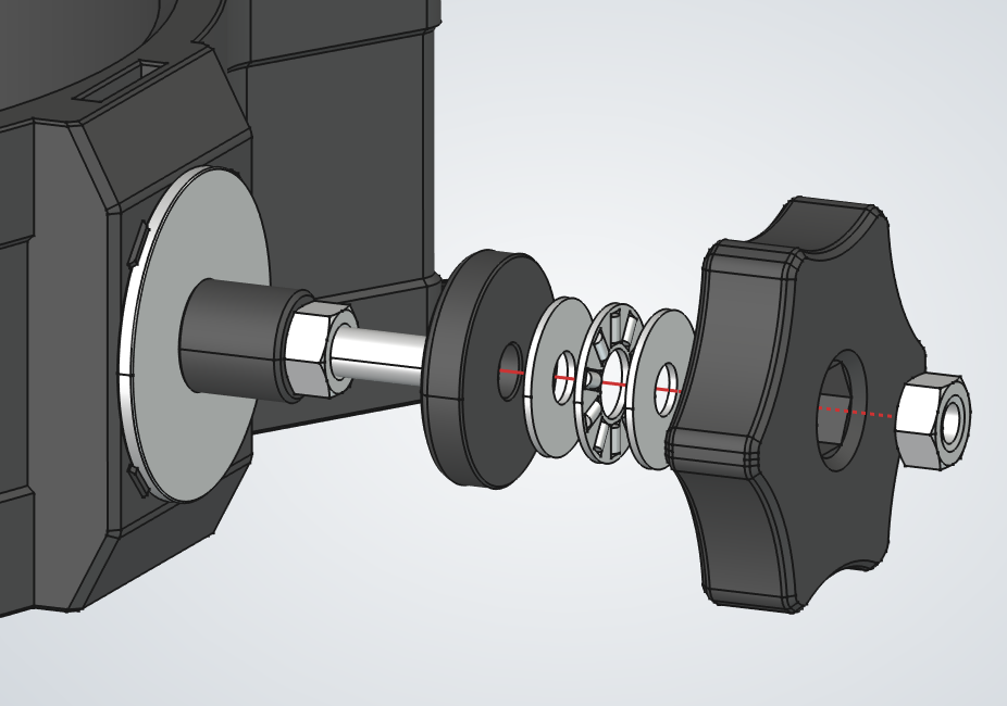
  1. 4.Build the handle stack.
    1. a.Add the printed washer with the recessed side facing the part.
    2. b.Add the 19mm washer.
    3. c.Add the bearing.
    4. d.Add another 19mm washer.
    5. e.Add the printed handle and nut.
    6. f.Tighten the handle just enough so it does not rattle.
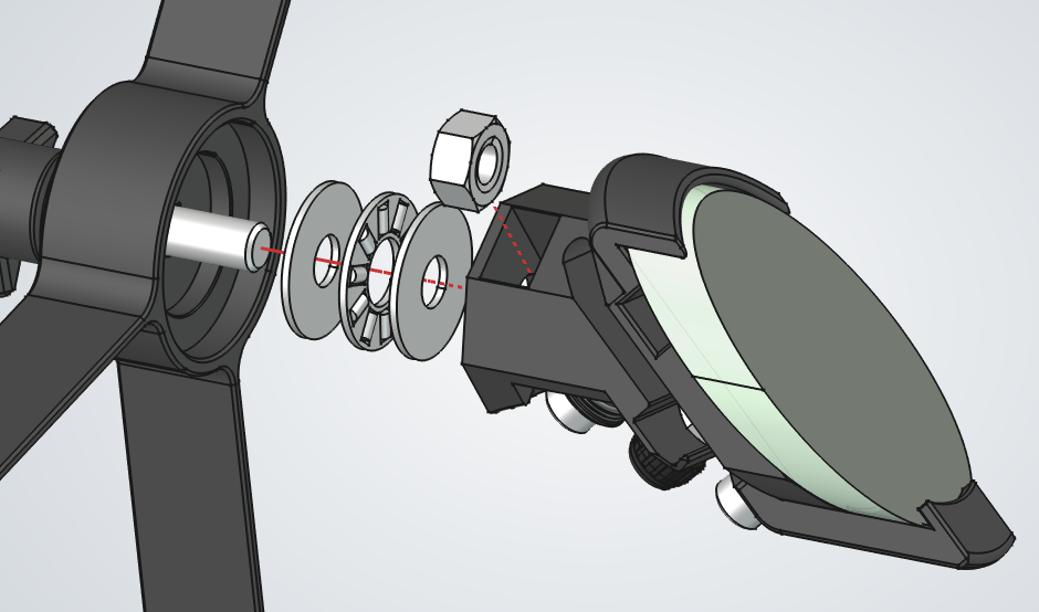
  1. 5.Repeat step 2 on the other side, this time with a 35mm hex screw.
  1. 6.Insert an M6 nut into the left axle's recess, then thread the axle onto the 35mm screw by hand until it locks in place.

Tube Clamp (x3)

PartQty
Tube clamp1Tube clamp thumbnail
M4 nut2M4 nut thumbnail
M4x30 thumbscrew1M4x30 thumbscrew thumbnail
M4x20 socket head screw1M4x20 socket head screw thumbnail
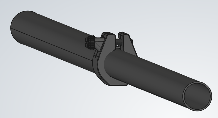
1Tube Clamp (x3) assembly
2Tube Clamp (x3) assembly
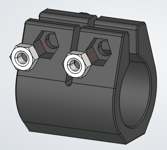
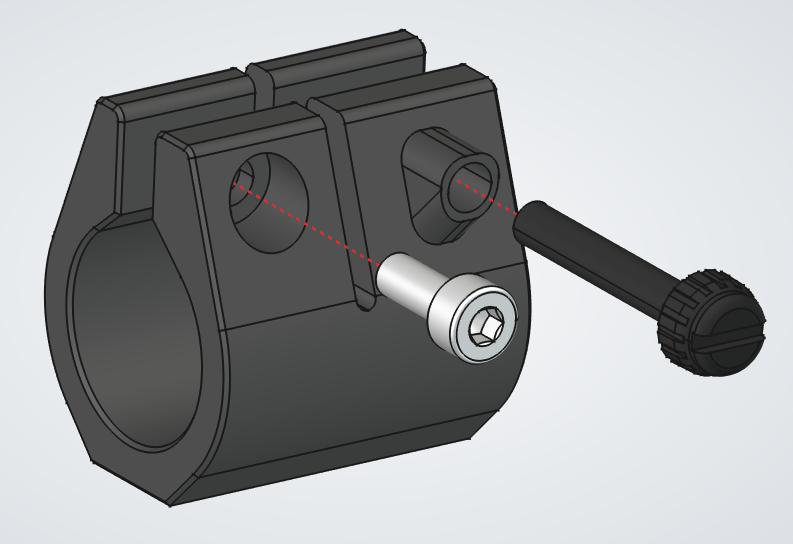
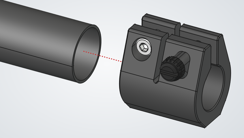
  1. 1.Insert the two M4 nuts into the top pockets of the clamp.
  2. 2.Insert the M4 screw and thumbscrew through the side holes, then thread them into the nuts.

Tube Assembly (x3)

PartQty
Tube clamp assembly1Tube clamp assembly thumbnail
Tube wide1Tube wide thumbnail
Tube narrow1Tube narrow thumbnail
PTFE sheet for tube1PTFE sheet for tube thumbnail
1Tube Assembly (x3) assembly
2Tube Assembly (x3) assembly
3Tube Assembly (x3) assembly
4Tube Assembly (x3) assembly
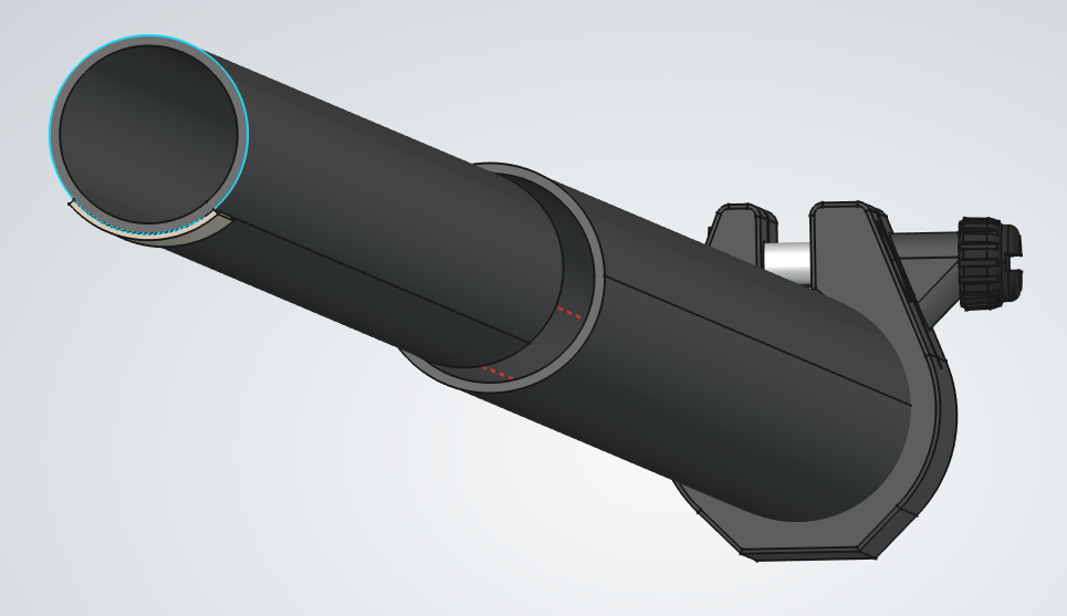
  1. 1.Slide a tube clamp onto the wider tube and tighten the M4 screw to hold it in place.
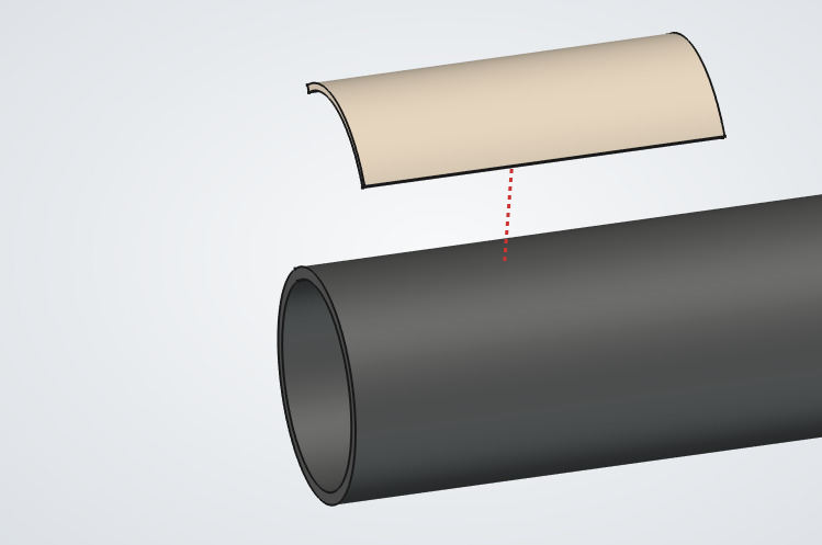
  2. 2.Cut a 3 cm by 1.5 cm piece from the PTFE sheet and stick it onto the outside edge of the narrow tube.
  3. 3.Insert the narrow tube from the back of the wider tube, with the PTFE piece on the side opposite the clamp, facing down.
  4. 4.Check that the narrow tube slides out until the PTFE piece reaches the clamp, then stops.
  5. 5.Tighten the clamp to keep the tube extended.
  6. 6.Repeat for the remaining tubes.

Secondary Cell

PartQty
Secondary cell1Secondary cell thumbnail
M4x20 socket head screw1M4x20 socket head screw thumbnail
M4 nut3M4 nut thumbnail
M4x10 thumbscrew1M4x10 thumbscrew thumbnail
Spring 0.9mm1Spring 0.9mm thumbnail
Secondary mirror1Secondary mirror thumbnail
Secondary cell tab1Secondary cell tab thumbnail
Secondary cell spring base1Secondary cell spring base thumbnail
M4x10 socket head screw1M4x10 socket head screw thumbnail
1Secondary Cell assembly
2Secondary Cell assembly
3Secondary Cell assembly
4Secondary Cell assembly
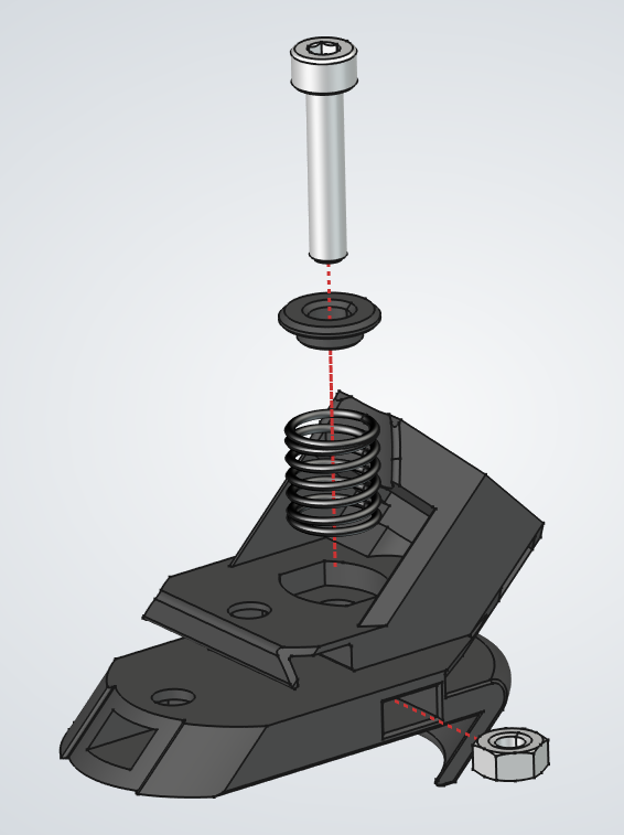
  1. 1.Install the spring
    1. a.Put the cell facing down like shown in image 1, and insert an M4 nut into the side pocket shown.
    2. b.Place a 0.9mm spring, the softer of the two spring types, in its recess.
    3. c.Add the spring base with its recess facing down, then place a 20mm screw on top.
    4. d.Press the spring down with one hand while using the Allen key in your other hand to tighten the screw.
    5. e.Watch the nut from the opposite side as the screw threads through it. Stop once the screw is fully engaged, before it protrudes past the nut.
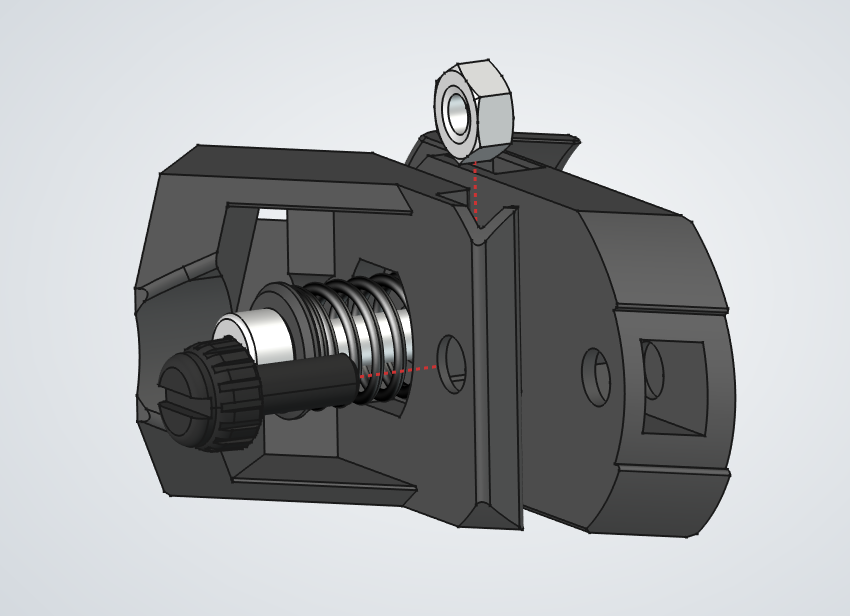
  1. 2.Install the thumbscrew and nut shown in image 2. Tighten it until it touches the other side, then tighten it another 1-2mm.
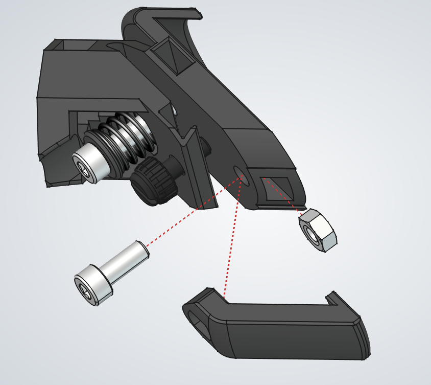
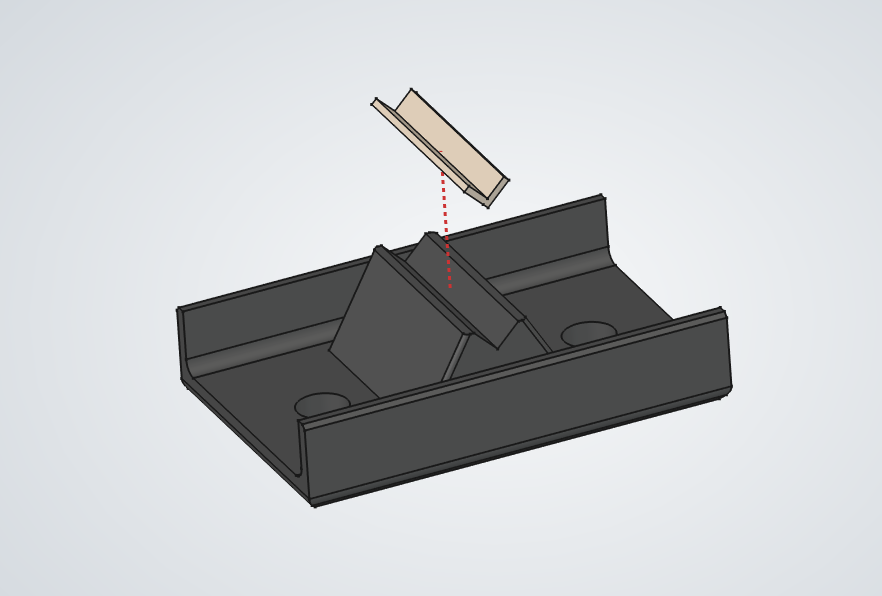
  1. 3.Install the secondary cell tab using an M4 nut and a 10mm screw. Keep it loose so the secondary mirror can be installed.
  1. 4.Install the secondary mirror.
    1. a.Single-use gloves are recommended for this step to avoid fingerprints on the mirror. With or without gloves, avoid touching the mirror surface.
    2. b.Place the mirror in its recess and make sure it is fully seated.
    3. c.Press the tab firmly against the mirror with one hand while using the Allen key in your other hand to tighten the tab's screw.
    4. d.Try to move the mirror to make sure it is held firmly. It should not move.
  1. 5.Cover the mirror cell with one of the velvet bags to keep the mirror clean during the next steps.

Spider

PartQty
Secondary cell assembly1Secondary cell assembly thumbnail
Secondary cell spider1Secondary cell spider thumbnail
M6x35 hex head screw1M6x35 hex head screw thumbnail
M8 washer 19mm wide4M8 washer 19mm wide thumbnail
Bearing AXK08192Bearing AXK0819 thumbnail
M4 nut3M4 nut thumbnail
Secondary cell spider knob1Secondary cell spider knob thumbnail
M6 nut1M6 nut thumbnail
1Spider assembly
2Spider assembly
3Spider assembly
  1. 1.From the front of the spider, install these parts through the center hole.
    1. a.M6x35 screw.
    2. b.Spider knob.
    3. c.Two 18mm washers.
  2. 2.On the other side of the spider, add these parts onto the screw.
    1. a.19mm washer.
    2. b.AXK bearing.
    3. c.Another 19mm washer.
  3. 3.Tighten the spider knob until the secondary cell turns only when you turn the knob, with firm friction and no free play.
  4. 4.Put the velvet bag over the secondary cell so the mirror stays clean for the rest of the assembly.
  5. 5.Insert the nuts into the pockets at the ends of the spider arms.

Focuser Knob

PartQty
Focuser knob2Focuser knob thumbnail
3 mmx60 pin13 mmx60 pin thumbnail
M4x10 socket head screw2M4x10 socket head screw thumbnail
M4 nut2M4 nut thumbnail
Silicone band 20x52Silicone band 20x5 thumbnail
Focuser Knob assembly
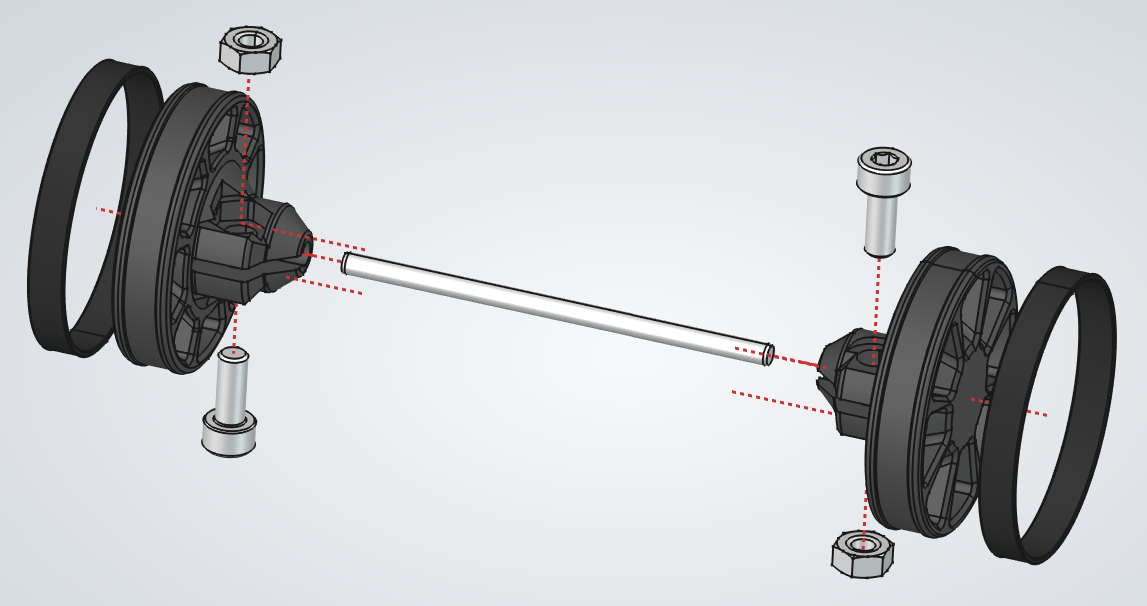
  1. 1.Install a screw and nut in each knob.
  2. 2.Fit the rubber bands onto the knobs.
  3. 3.Slide the knobs onto the shaft until fully seated, then tighten the screws to clamp them in place.

Focuser Base

PartQty
Focuser base1Focuser base thumbnail
Bearing 6042RS4Bearing 6042RS thumbnail
M4x10 socket head screw4M4x10 socket head screw thumbnail
Focuser Base assembly
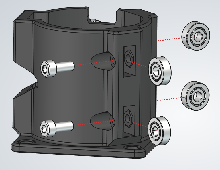
  1. 1.Place a bearing in one of the bearing pocket on the base.
  2. 2.Insert the M4 screw through the bearing and into the opposite side of the pocket.
  3. 3.Tighten the screw into the plastic until the screw lip seats in place.
  4. 4.Check that the bearing still spins freely.
  5. 5.Repeat for the other bearings.

Focuser Tube

PartQty
Focuser tube1Focuser tube thumbnail
M4x10 thumbscrew1M4x10 thumbscrew thumbnail
M4 nut1M4 nut thumbnail
Aluminum rail for focuser3Aluminum rail for focuser thumbnail
1Focuser Tube assembly
2Focuser Tube assembly
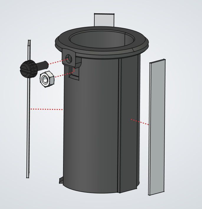
  1. 1.Install the thumbscrew and captive nut in the focuser tube.
  2. 2.For each rail, peel off the double-sided tape backing and place the rail on the tube.
  3. 3.Align each rail with the shallow groove in the tube.
  4. 4.Press each rail firmly for a few seconds so the tape bonds well.
  5. 5.Do not worry about the tape strength. It only needs to hold the rails during assembly, the pressure from the bearing will keep them in place.

Focuser Bridge

PartQty
Focuser bridge1Focuser bridge thumbnail
PTFE sheet for focuser1PTFE sheet for focuser thumbnail
Focuser Bridge assembly
  1. 1.Cut a 1.5 cm by 0.8 cm piece from the PTFE sheet.
  2. 2.Peel off the backing and stick the PTFE piece into the recess on the bridge.
  3. 3.Use the long shaft of the Allen key to press it down firmly so it takes the shape of the recess.

Focuser

PartQty
M4x10 thumbscrew2M4x10 thumbscrew thumbnail
M4 nut2M4 nut thumbnail
Focuser bridge assembly1Focuser bridge assembly thumbnail
Focuser knob assembly1Focuser knob assembly thumbnail
Focuser tube assembly1Focuser tube assembly thumbnail
Focuser base assembly1Focuser base assembly thumbnail
1Focuser assembly
2Focuser assembly
3Focuser assembly
  1. 1.Insert an M4 nut into the top pocket in the base. From the other side, thread the thumbscrew through the focuser bridge and the knob into the nut.
  2. 2.Add the lower thumbscrew and nut the same way. Tighten both thumbscrews only enough to keep the assembly from falling apart.
  3. 3.Slide the focuser tube into the base. The thumbscrew should fit into the pocket in the base so the tube can reach all the way down.
  4. 4.Tighten the bridge thumbscrews until the tube moves smoothly when you turn the knob, even while pressing down on the tube.

Finder Mount

PartQty
Finder mount1Finder mount thumbnail
M4x10 socket head screw2M4x10 socket head screw thumbnail
M4x10 thumbscrew1M4x10 thumbscrew thumbnail
M4 nut1M4 nut thumbnail
Finder Mount assembly
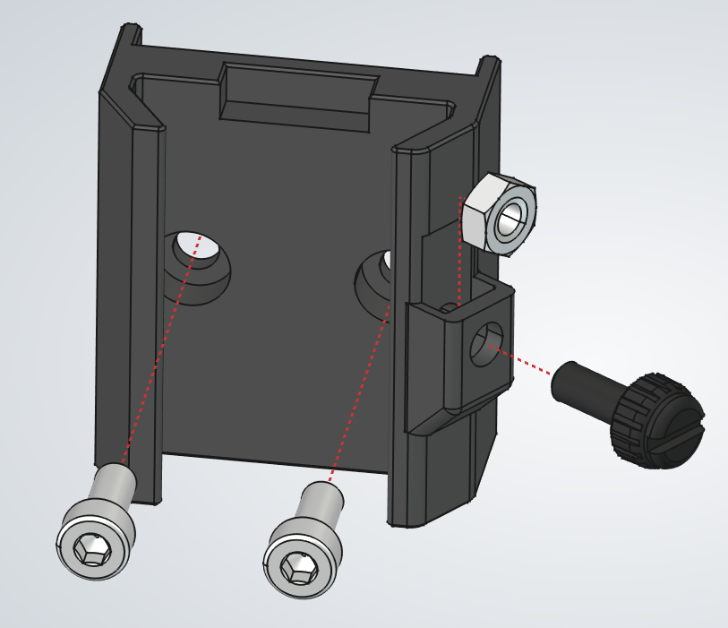
  1. 1.Insert the M4 nut into its pocket, then thread the thumbscrew into it.
  2. 2.Insert the two M4 screws that will later attach the mount to the top assembly.

Preparing the Finder

PartQty
Red dot finder1Red dot finder thumbnail
1Preparing the Finder assembly
2Preparing the Finder assembly
3Preparing the Finder assembly
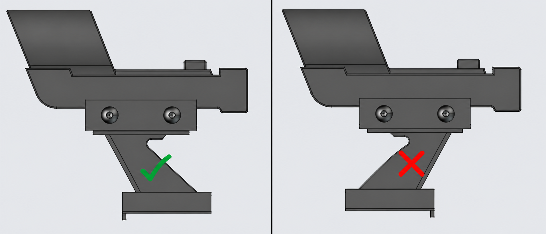
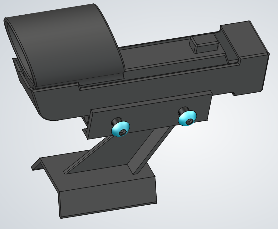
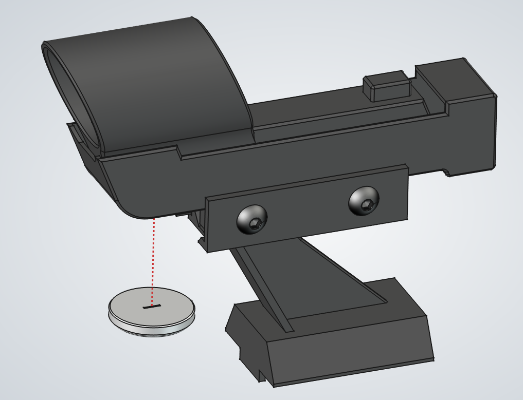
  1. 1.First, flip the finder on its stem so the small tab sits at the front. This helps keep the finder from sliding off its mount. The first image shows the correct orientation versus the incorrect one.
    1. a.Loosen the two side screws on the finder just enough to slide the base off.
    2. b.Flip the base so the side with the small tab faces forward.
    3. c.Slide the base back into the finder and tighten the two side screws.
  2. 2.Install the battery in the compartment at the front.

Top Assembly

PartQty
Telescope top1Telescope top thumbnail
M4 nut13M4 nut thumbnail
Finder mount assembly1Finder mount assembly thumbnail
M4x10 thumbscrew7M4x10 thumbscrew thumbnail
Focuser assembly1Focuser assembly thumbnail
M4x10 socket head screw7M4x10 socket head screw thumbnail
Spider assembly1Spider assembly thumbnail
Light shield1Light shield thumbnail
Red dot finder1Red dot finder thumbnail
1Top Assembly assembly
2Top Assembly assembly
3Top Assembly assembly
4Top Assembly assembly
5Top Assembly assembly
6Top Assembly assembly
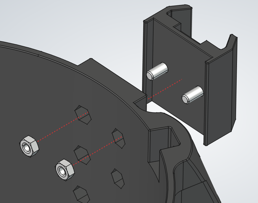
  1. 1.Insert the two nuts and screws into their pockets in the tube slot. Repeat for all three sides.
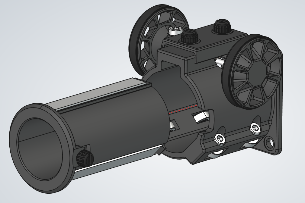
  1. 2.Attach the finder mount to the accessory rail with the recessed side facing up.
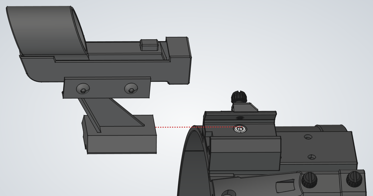
  1. 3.Seat the finder in its mount and lock it with the mount's thumbscrew.
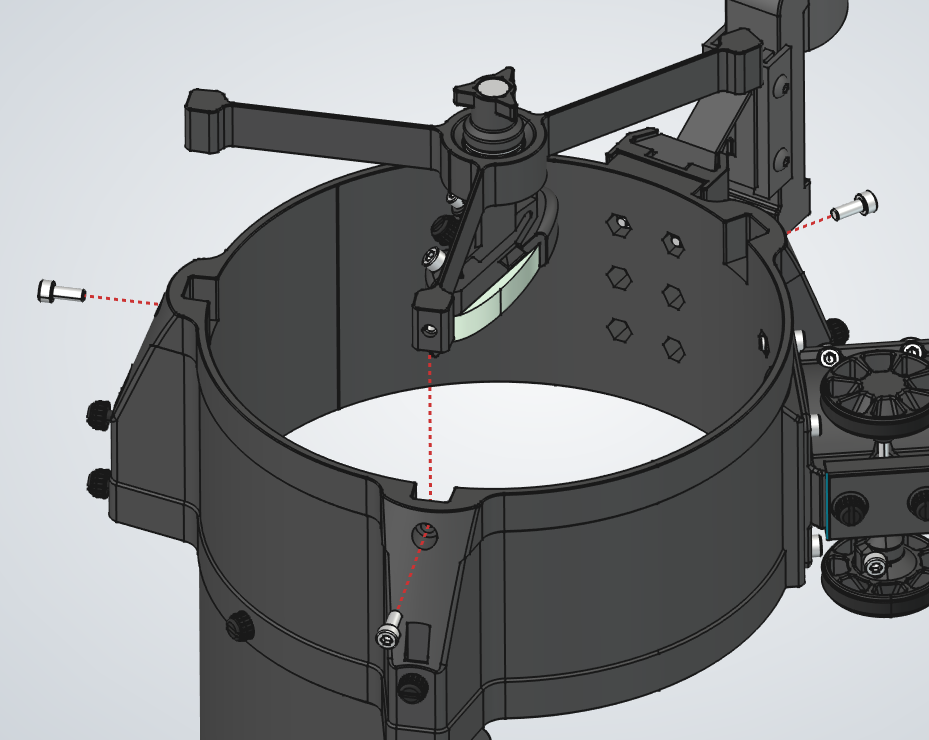
  1. 4.Mount the focuser assembly with four M4 nuts. Face the handle away from the tube slot near the focuser, as shown.
  1. 5.Install the spider assembly and secure it with three M4 screws.
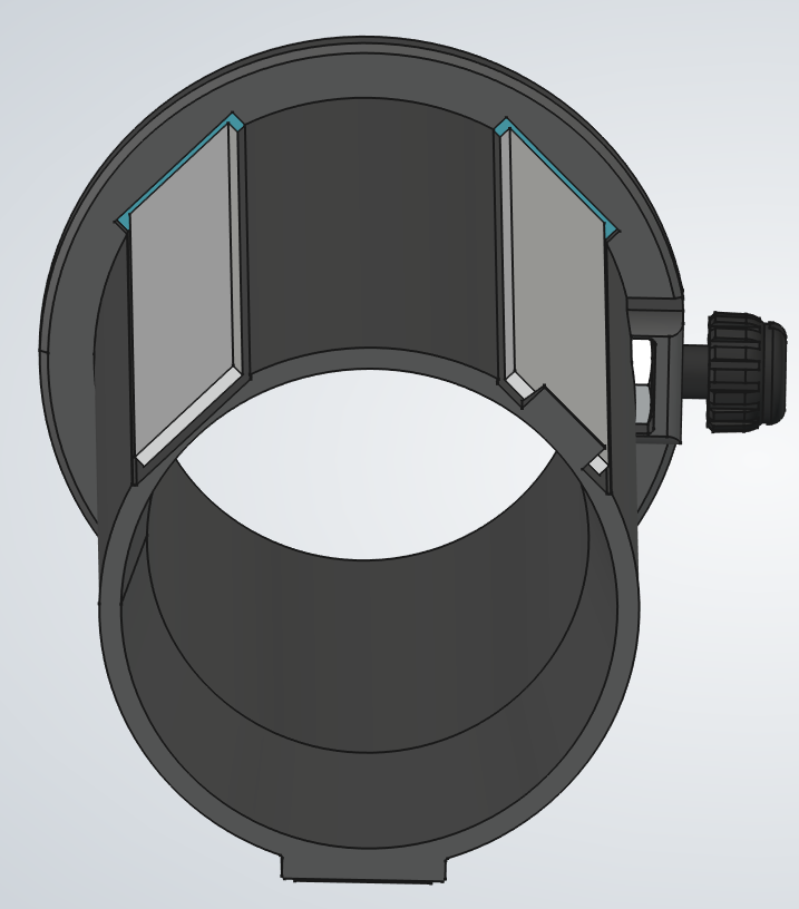
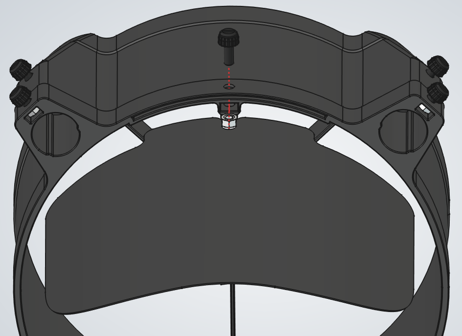
  1. 6.Install the nut and screw for the light shield, then install the light shield.

Telescope Assembly

PartQty
Telescope bottom assembly1Telescope bottom assembly thumbnail
Telescope center assembly1Telescope center assembly thumbnail
Tube assembly3Tube assembly thumbnail
Telescope top assembly1Telescope top assembly thumbnail
1Telescope Assembly assembly
2Telescope Assembly assembly
3Telescope Assembly assembly
4Telescope Assembly assembly
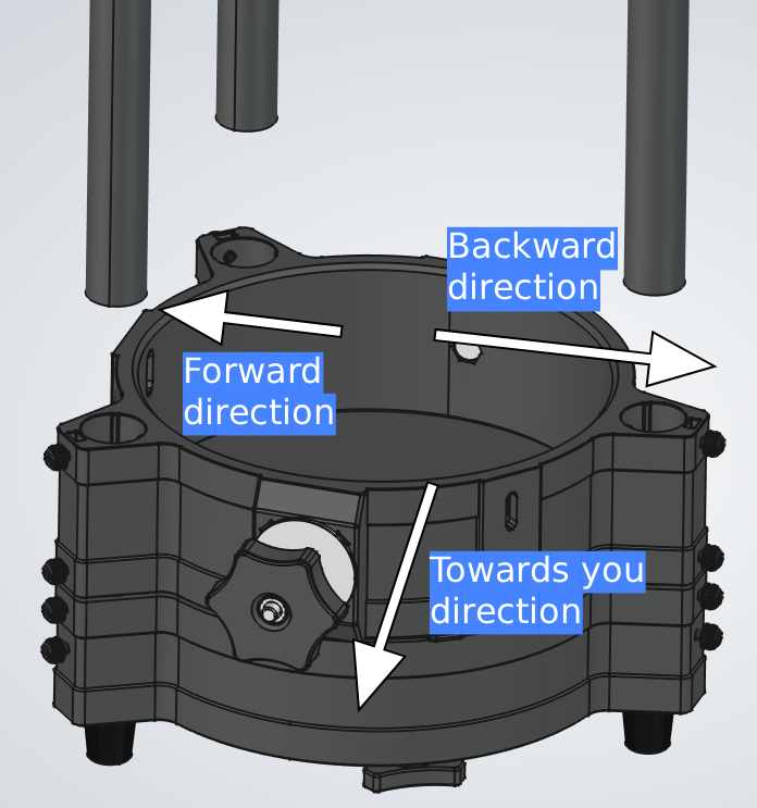
  1. 1.Place the bottom assembly on your build surface, aligned as shown in image 1.
  2. 2.Place the center assembly on top of it with the handle facing you.
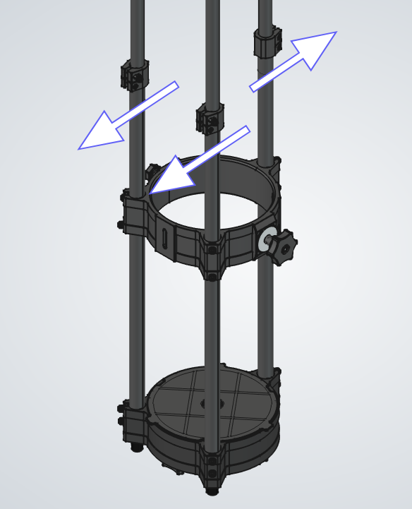
  3. 3.Insert the tubes through both assemblies, making sure they slide all the way down and do not get caught on the thumbscrews.
  1. 4.Rotate the tubes so the bottom clamps face forward and the top one faces backward, as shown in image 2.
  2. 5.Lock the thumbscrews on the bottom assembly.
  3. 6.Slide the center assembly up about 30cm (1 ft).
  4. 7.Lock some of the center assembly's thumbscrews. Not all are needed yet, since we will adjust the distance later.
  1. 8.By now, all three tubes should be extended from the earlier steps. Keep only the back one extended, and retract the other two halfway so they will not interfere.
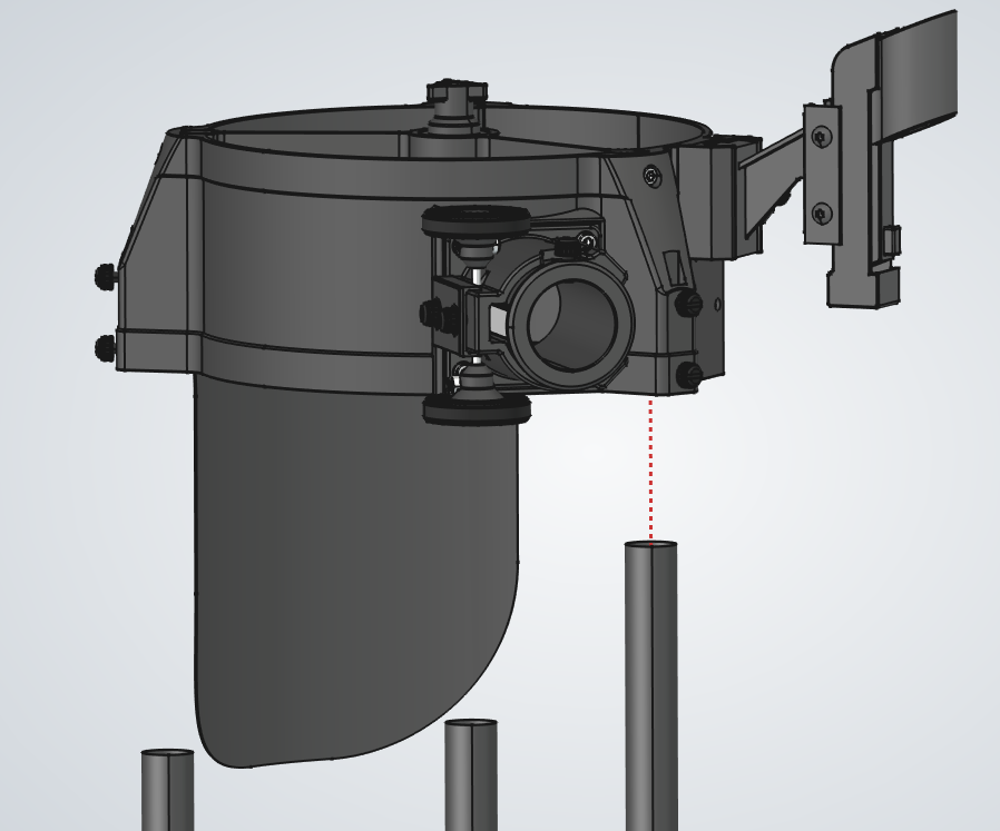
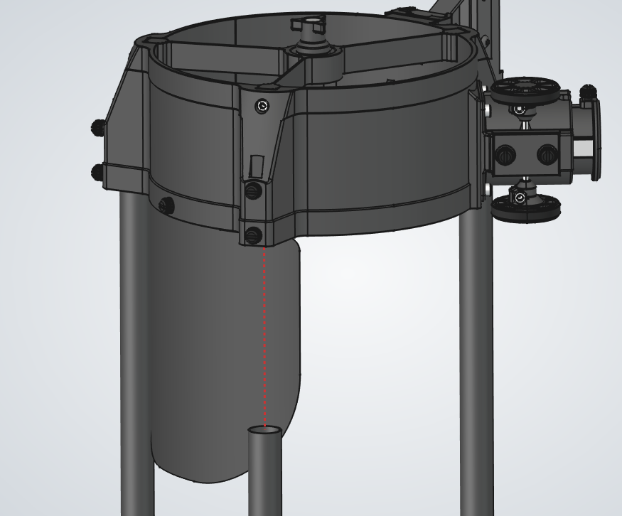
  2. 9.Place the top assembly on the tube and lock the thumbscrew, making sure it is fully seated.
  3. 10.Extend the other two tubes, then insert and lock their thumbscrews.
  4. 11.Now you can collapse the whole telescope:
    1. a.Unlock the clamps and collapse the telescope.
    2. b.Lock the clamps again.
    3. c.As you do this, the light shield will slide above the clamp and will not interfere.